Tuesday, 11 October 2011

12 Volts Transformerless Power Supply


This 12 Volts transformerless power supply take advantage of the fact that a Zener diode is also a normal diode that conducts current in the forward direction. During one half wave, the current flows via D1 through the load and back via D4, while during the other half wave it flows via D3 and D2. Bear in mind that with this circuit (and with the bridge rectifier version), the zero voltage reference of the DC voltage is not directly connected to the neutral line of the 230-V circuit.
The amount of current that can be delivered depends on the capacitance of C1. With the given value of 220nF, the current is approximately 15mA. A final warning: this sort of circuit is directly connected to mains voltage, which can be lethal. You must never come in contact with this circuit! It is essential to house this circuit safely in a suitable enclosure.

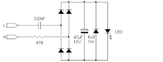
Flashing LEDs


Flashing LEDs

Powering a flashing LED from this circuit. Flashing LEDs have two undesirable traits; They change the drive current when 'off', and do not like the supply voltage falling to zero during cycle change over. In the circuit below, two components are added to cater for this difference; There is a smoothing cap to help keep the supply voltage above zero while the supply current changes phase, and a zener to help regulate the output voltage while the LED is off and drawing very little current. The above values were successfully used on more than one occasion.

36 LED String on 240VAC


36 LED String on 240Volt AC
36*3.2= 115 Volts
240*√2= 336 volts (peak value)
240 input voltage produce 336 volt peak value but we can use RMS value to select correct resistor.
with this approximation:
use one diode bridge rectifier to 240 volt and use one resistor about (240-115)/20mA= 6K = 6.2 Kohm in input path.
resistor power dissipation will be 125*125/6.2K=2.5Watts
(use minimum 5W for resistor)
also you can use one resistor and one capacitor (in series) in place of resistor.
in this case power dissipation in resistor is lower.

Important note:
this formulas are not precise for this application,
because voltage on resistor isnt sinosoidal, but
for first try we can use these.